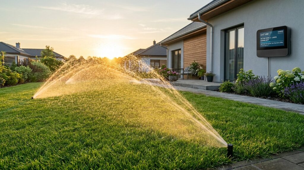
Wiring a modern smart sprinkler controller requires understanding low-voltage AC circuitry, shared return conductors, and solenoid valve electrical characteristics. This comprehensive technical guide walks through identifying common wires, diagnostic multimeter benchmarking, and migrating legacy mechanical timers to intelligent multi-zone irrigation controllers without risking blown transformers or damaged driver triacs.
Automated irrigation systems rely on 24-volt alternating current (VAC) to actuate electromagnetic solenoids attached to hydraulic diaphragm valves. When upgrading from legacy electro-mechanical dial timers (such as vintage Rain Bird or Toro clocks) to cloud-connected smart controllers (such as Rachio 3, Hunter Pro-HC, or Rain Bird ESP-TM2), field wiring errors account for more than 75% of post-installation system faults. The most frequent failure points include misidentified common wires, undersized gauge runs causing severe voltage drops across distant lateral zones, and undetected coil shorts that incinerate controller output solid-state switches.
Irrigation Electrical Fundamentals: 24VAC Low-Voltage Circuits
Unlike residential split-phase 120V/240V direct-current electronics, standard residential and commercial turf irrigation operates on low-voltage 24VAC power. The power source is typically an external or internal step-down transformer converting 120VAC line voltage down to an open-circuit secondary voltage between 26VAC and 28VAC. Under standard load, this potential settles between 24VAC and 25.5VAC.
Every active zone requires a closed electrical circuit consisting of three primary elements:
- The Zone Hot Lead: An insulated copper conductor running from a dedicated terminal screw or push-connector on the controller backplane directly to one lead of an individual zone valve solenoid.
- The Solenoid Coil: An inductive electromagnetic actuator mounted atop the valve bonnet. Inside, copper magnet wire creates a magnetic field when energized, retracting a spring-loaded stainless steel plunger to relieve pilot pressure above the valve diaphragm.
- The Common Return Conductor: A shared return path connecting the secondary lead of every valve solenoid back to the “C” or “COM” terminal on the controller. In virtually all North American installations, this wire is color-coded white.
| Specification / Parameter | Standard 24VAC Solenoid Valve | High-Efficiency Low-Power Solenoid | Diagnostic Tolerance Range |
|---|---|---|---|
| Static Coil Resistance (DC Ohms) | 20 Ω – 60 Ω | 35 Ω – 45 Ω | Values < 15 Ω indicate short; > 80 Ω indicate partial break |
| Inrush Current (Initial Stroke) | 350 mA – 450 mA (0.35 – 0.45 A) | 200 mA – 280 mA (0.20 – 0.28 A) | Peak draw lasting 15 to 40 milliseconds |
| Holding Current (Sustained Open) | 180 mA – 250 mA (0.18 – 0.25 A) | 100 mA – 140 mA (0.10 – 0.14 A) | Continuous thermal load on controller triac/relay |
| Minimum Actuation Voltage | 19.0 VAC | 18.0 VAC | Measured directly at solenoid terminals during inrush |
Decoding Field Wire Bundles: Identifying the Common Wire
When unfastening a legacy timer, you will typically encounter a multi-conductor direct-burial cable (UF-B or irrigation-rated multi-strand cable, typically 18/4, 18/8, or 18/12 AWG). While modern best practices mandate white insulation for the common wire, vintage or contractor-installed systems frequently defy standardized color coding.
Never rely exclusively on wire insulation color. Contractors occasionally use green (standard for master valves), black, or even repurposed station conductors for common returns when original wires suffer shear damage underground. The only definitive method for verifying field wiring is empirical bench testing using a digital multimeter.
| Conductor Insulation Color | Standard Industry Purpose | Alternative / Field Variation | Verification Method |
|---|---|---|---|
| White | Zone Common Return (COM / C) | Occasionally used for Zone 1 in non-standard installs | Verify resistance against all other colored conductors |
| Red, Blue, Green, Orange, Brown | Individual Zone Station Hot Leads | Assigned to Zones 1 through 12 sequentially | Displays 20–60 Ω when paired against Common |
| Yellow or Dark Blue | Master Valve / Pump Start Relay (P/MV) | Often routed into dedicated P/MV terminal | Powers high-current pump contactor coil |
| Bare Copper or Green | Earth Ground (Controller Chassis) | Never connected to 24VAC valve circuitry | Bonded to dedicated earth ground rod for surge mitigation |
Multimeter Benchmarking: Step-by-Step Diagnostic Protocol
To safely identify field conductors without powering the system or risking controller damage, follow this diagnostic isolation sequence:
- De-energize the Existing Controller: Disconnect the 120VAC plug or switch off the dedicated circuit breaker powering the irrigation timer.
- Disconnect All Field Leads: Remove all field wires from the terminal blocks. Label each wire with masking tape according to its original terminal position before removal.
- Configure Digital Multimeter: Set the rotary dial to resistance measurement (Ohms, Ω), utilizing the lowest range (such as 200Ω) or auto-ranging mode. Touch the test probes together; verify that the meter zeroes out (displaying 0.1Ω to 0.3Ω lead resistance).
- Locate the Common Conductor via Matrix Testing:
- Fasten the black reference probe to the suspected white Common wire.
- Probe each colored zone wire individually with the red probe.
- If the reference conductor is indeed the true common return, every healthy zone conductor will register between 20Ω and 60Ω.
- If you accidentally fastened your black probe to an active station lead rather than the common, only the common wire will read normal resistance (20–60Ω), while probing another station lead will display twice the normal resistance (40–120Ω, measuring two solenoids wired in series through the common junction), or open loop (O.L.).
Master Valves and Pump Start Relays: Critical Wiring Nuances
Many suburban and agricultural irrigation systems feature an upstream master valve installed before the individual zone manifolds, or an auxiliary pump start relay connecting a shallow well to the controller. The master valve remains closed until any individual zone is scheduled to run, preventing catastrophic flooding in the event of an underground mainline pipe rupture.
When migrating to a smart controller:
- Master Valve Terminals (M / MV / P/MV): Connect the dedicated master valve lead to the terminal marked P/MV. In software configuration, enable the Master Valve toggle. The controller will simultaneously energize the P/MV terminal and the active zone terminal during irrigation cycles.
- Pump Start Relay Coil Current Restrictions: Smart irrigation controllers typically provide between 0.8A and 1.0A total power across all simultaneous outputs. Heavy-duty magnetic contactors in legacy pump boxes can pull inrush currents exceeding 1.2A, which triggers automatic overcurrent trip faults on smart controllers. If your pump start relay exceeds 0.6A holding current, install an interposing low-power 24VAC isolation relay between the controller and the pump starter.
Rain and Soil Moisture Sensor Integration
Legacy rain clicks typically use normally-closed (N.C.) mechanical micro-switches driven by hydroscopic cork discs that expand when wet. While smart controllers utilize cloud-based weather forecasting (evapotranspiration modeling), retaining a local physical rain freeze sensor or in-ground soil moisture sensor provides essential localized overrides during unpredicted downpours.
When connecting sensors to smart controller sensor terminals (S1, S2, 24V-, 24V+):
- Remove the pre-installed brass or wire jumper between the sensor terminals (often marked “SEN” and “C” or “S1” and “S2”). Leaving the jumper intact bypasses the sensor circuit entirely.
- For passive two-wire rain sensors, polarity does not matter. Fasten one lead to S1 and the other to SC (Sensor Common) or S2.
- For active 24V powered wireless rain/freeze sensors (such as Hunter Wireless Rain-Clik or Irritrol RainSensor), connect the two yellow power leads to the controller 24VAC power terminals, the white lead to Sensor Common, and the brown/orange lead to the active sensor input.
Field Troubleshooting Matrix: Diagnosing Common Electrical Faults
| Symptom Observed | Root Electrical Cause | Diagnostic Multimeter Reading | Corrective Action |
|---|---|---|---|
| Zone will not activate; water flow absent | Open circuit / Severed field wire or dead solenoid coil | Infinite resistance (O.L. / Open Loop) across Common and Zone lead | Inspect wire splices inside valve box; replace corroded wire nuts with waterproof silicone gel-filled connectors. Replace solenoid if coil is open. |
| Controller reports Zone Fault / Overcurrent Shutdown | Short circuit in solenoid winding or abraded wire grounded to wet soil | Resistance below 12 Ω (typically 0.2 Ω to 4.0 Ω) | Isolate zone immediately to protect controller triac. Unscrew solenoid, inspect for thermal blistering, install new 24VAC solenoid. |
| Two zones activate simultaneously whenever either is called | Field wiring short bridging two station conductors together | Near 0 Ω resistance between two station leads when Common is disconnected | Locate underground physical damage caused by aerator, trenching, or rodent activity; splice in fresh multi-conductor segment. |
| All zones fail simultaneously after controller upgrade | Common wire disconnected or loose at manifold junction | O.L. across all zone wires when tested against Common terminal | Re-strip Common wire end, inspect master wire-nut splice inside primary manifold valve box, tighten terminal screw. |
Anthbot Wire-Free RTK + 4-Camera Vision Robotic Lawn Mowers
Eliminate perimeter boundary wire installation with centimeter-accurate RTK satellite positioning, 300-degree quad-camera obstacle avoidance, and automated multi-zone lawn management.
Explore Anthbot Official Store & Current Pricing →