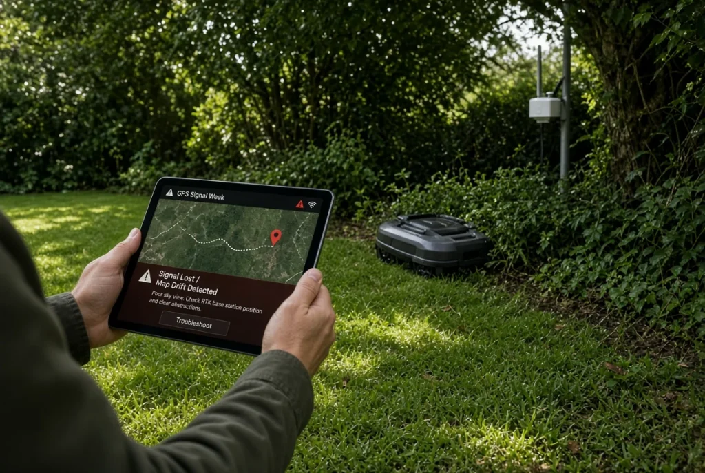
Deploying a wire-free autonomous robotic lawn mower hinges on establishing an uncompromised Real-Time Kinematic Global Navigation Satellite System (RTK-GNSS) reference base station. While standard consumer GPS provides location estimates with three to five meters of atmospheric drift, RTK base stations utilize double-differenced carrier-phase calculations to achieve repeatable positioning down to plus or minus two centimeters. This technical deployment guide details the radio frequency physics, elevation masking, antenna grounding, and multipath mitigation protocols necessary to ensure persistent positioning fix for autonomous turfcare equipment.
The Physics of Real-Time Kinematic Carrier-Phase Positioning
To understand why RTK antenna placement determines autonomous mower reliability, turf managers must evaluate the core mechanics of satellite radiolocation. Standard single-receiver GPS measures pseudorange, calculating distance by correlating binary coarse-acquisition (C/A) pseudorandom noise codes transmitted on the L1 frequency band (1575.42 MHz). Because the radio signals traverse variable ionospheric plasma densities and tropospheric moisture layers, clock timing errors and atmospheric delays introduce positional drift between two and five meters.
Pseudorange GPS vs Double-Differenced Carrier Phase (2-Centimeter Fix)
Real-Time Kinematic positioning replaces coarse code timing with direct measurement of the satellite radio carrier waves themselves. The wavelength of the L1 carrier wave is approximately 19.0 centimeters, while the secondary L2 (1227.60 MHz) and L5 (1176.45 MHz) carrier waves span roughly 24.4 and 25.5 centimeters respectively. By counting the complete integer number of sinusoidal radio waves between the satellite and the ground antenna, plus measuring the fractional phase remainder down to a millimeter fraction, the system eliminates atmospheric delay variables.
This precision requires double-differencing equations. By calculating the difference in carrier phase between two distinct satellites observed simultaneously by two independent receivers—the stationary reference base station and the moving robotic mower rover—the receiver algorithms cancel out receiver clock bias, satellite clock error, and regional ionospheric refraction. The result is a relative baseline coordinate vector accurate to within 15 to 20 millimeters.
Fix vs Float Status: Why Integer Ambiguity Resolution Fails
In autonomous mowing telemetry, the rover status toggles between two primary mathematical states:
- RTK Fix (Centimeter Precision): The mathematical filter has solved the integer ambiguity problem, determining the exact integer number of carrier cycles between the satellites and both receivers. The mower navigates within a horizontal tolerance of 2.0 centimeters, permitting border trimming along patio edges and pool decks.
- RTK Float (Decimeter Uncertainty): The algorithm has not resolved the integer cycle count with statistical certainty and operates on probabilistic real-number estimates. Positional uncertainty expands to 20 to 80 centimeters. In float mode, autonomous mowers must decelerate or pause mowing along boundary corridors to prevent physical intrusion into garden beds or hardscape hazards.
Integer ambiguity resolution fails when satellite signals experience physical obstruction, low signal-to-noise ratios (SNR < 32 dB-Hz), or severe multipath reflection.
Upgrade Your RTK Reception: Commercial Antenna Mast Kits
Elevate your GNSS base station above rooflines and tree cover with heavy-duty galvanized extension masts and weatherproof 915 MHz LoRa range extenders.
View RTK Masts & Hardware Accessories →Site Survey and Antenna Siting: The 15-Degree Horizon Rule
The cardinal rule of RTK base station installation is selecting a mounting location that maintains an unobstructed 360-degree hemispherical view of the sky above a 15-degree elevation mask angle.
Fresnel Zone Clearances and Overhead Foliage Attenuation
Electromagnetic signals at microwave frequencies (1.1 to 1.6 GHz) do not penetrate dense biological matter without severe signal attenuation and phase disturbance. Wet tree leaves, dense coniferous needle canopies, and water-retaining deciduous foliage introduce signal absorption and scattering. When satellite radio waves pass through wet tree leaves, the signal attenuation can exceed 12 dB per meter of canopy depth.
To avoid signal degradation, establish clear line-of-sight across the first Fresnel zone. Elevate the base station antenna mast so that the conical viewing angle above 15 degrees from the horizontal horizon remains clear of overhanging branches within a six-meter radial perimeter. Siting the antenna on the highest gable peak or chimney collar of a residential dwelling ensures that low-elevation satellites emerging over the horizon are tracked immediately.
Identifying and Mitigating Metallic and Structural Multipath Reflectors
Multipath interference represents the primary source of integer ambiguity corruption in residential settings. Multipath occurs when a satellite radio wave reflects off a nearby conductive surface—such as metal standing-seam roofs, aluminum siding, commercial HVAC enclosures, or solar photovoltaic panels—before reaching the antenna element.
Because the reflected path is longer than the direct line-of-sight vector, the carrier phase arrives delayed, corrupting the double-difference mathematical matrix. To mitigate multipath:
- Maintain a minimum separation distance of 2.5 meters between the GNSS antenna and vertical reflective walls or rooftop solar panel arrays.
- Deploy antennas equipped with an internal or external ground-plane choke ring. Choke rings create an electromagnetic impedance barrier that attenuates signals arriving from negative or low-elevation reflection angles.
- Set the software receiver elevation mask angle to 15 degrees in the configuration app, filtering out noisy low-horizon satellites that bounce off neighboring driveways or roofs.
| GNSS Constellation & Band | Carrier Frequency (MHz) | Wavelength (λ) | Minimum C/N0 Threshold | Functional Role in RTK Solution |
|---|---|---|---|---|
| GPS L1 C/A | 1575.42 MHz | 19.03 cm | 38 dB-Hz | Primary coarse acquisition and legacy integer baseline |
| GPS L5 | 1176.45 MHz | 25.48 cm | 35 dB-Hz | High-power aeronautical band; superior foliage penetration |
| Galileo E1 / E5a | 1575.42 / 1176.45 MHz | 19.03 / 25.48 cm | 36 dB-Hz | European constellation; excellent geometry at high latitudes |
| GLONASS G1 / G2 | 1602.00 / 1246.00 MHz | 18.71 / 24.06 cm | 34 dB-Hz | FDMA frequency diversity across polar orbital planes |
| BeiDou B1I / B2a | 1561.098 / 1176.45 MHz | 19.20 / 25.48 cm | 36 dB-Hz | Geostationary and MEO satellites providing high azimuth density |
Radio Link Engineering: 915 MHz LoRa Telemetry vs Network NTRIP
The base station must broadcast its calculated correction data to the robot rover at a minimum update frequency of 1 Hz (once per second). Two primary transmission protocols dominate modern autonomous equipment: dedicated sub-GHz radio links and cellular internet NTRIP casters.
Antenna Polarization, Ground Planes, and RF Gain Matching
Most consumer and prosumer robotic mowers (such as the Mammotion Luba 2 AWD and Husqvarna EPOS systems) utilize local 915 MHz LoRa (Long Range) spread-spectrum telemetry radios in North America (or 868 MHz in Europe). LoRa provides high receiver sensitivity (-135 dBm), enabling telemetry reception across complex topographies.
Ensure that both the base station transmitter antenna and the rover receiver whip antenna maintain strict vertical polarization. Aligning polarization prevents the 20 dB cross-polarization signal attenuation that occurs when a transmitter dipole tilts horizontally relative to the receiver.
When selecting aftermarket omnidirectional high-gain antennas, match the gain to the property topography:
- 3 dBi Omni-Dipole: Produces a spherical donut radiation pattern with broad vertical beamwidth (approx. 60 degrees). Ideal for rolling or multi-tiered properties with significant vertical elevation differences between rooftops and low turf valleys.
- 5.8 dBi High-Gain Collinear: Compresses the radiation pattern into a flat, horizontal disc with narrow vertical beamwidth (approx. 25 degrees). Ideal for expansive, flat multi-acre turf areas requiring transmission distances exceeding 1,000 meters.
Overcoming Distance Limits and Non-Line-of-Sight RF Attenuation
While 915 MHz signals diffract around obstacles better than 2.4 GHz Wi-Fi, thick masonry structures, detached steel garages, and dense cedar hedges cause radio-frequency shadow zones. If your rover mower reports frequent “Telemetry Link Timeout” warnings while maintaining clear sky view, evaluate deploying an external LoRa repeater or switching to a localized Networked Transport of RTCM via Internet Protocol (NTRIP) cellular caster over 4G LTE IoT SIM cards.
Step-by-Step Installation Blueprint: Masts, Grounding, and Power Wiring
A mechanically unstable base station destroys RTK accuracy. If an antenna mast sways by three centimeters in high winds, that physical deflection is transmitted directly into the correction stream as false rover coordinate error.
Rooftop J-Pole Mounting and Vibration Damping
Follow this systematic installation protocol to establish a rigid, permanent geodetic monument:
- Hardware Selection: Use a 1.5-inch outer diameter heavy-gauge galvanized steel J-pole mount or an antenna tripod secured with stainless steel lag bolts into roof rafters or masonry fascia boards. Never clamp the antenna to plastic plumbing vent pipes or lightweight gutter trim.
- Mechanical Bracing: For mast extensions exceeding 1.2 meters, install secondary triangulated strut arms to prevent flex and wind vibration during storm events.
- Plumb Calibration: Use a magnetic spirit torpedo level on two orthogonal planes (90 degrees apart) to ensure the mast is plumb before securing locking collar bolts.
Power-Over-Ethernet (PoE) and Solar Buffer Battery Integration
Running power to elevated rooftop positions requires careful electrical planning:
- PoE Deployment: For units supporting Ethernet transmission, utilize shielded outdoor-rated Cat6 (STP) cabling with UV-resistant PE jackets. Power the device using an IEEE 802.3af PoE injector installed inside the conditioned space.
- Solar Buffer Kits: For detached installations on outbuildings or property corners without mains power, install a 40W monocrystalline solar panel paired with a 12V 18Ah LiFePO4 battery pack and an MPPT charge controller. Ensure the battery capacity provides at least 72 hours of autonomy to sustain base station operation through consecutive overcast winter days.
Lightning Protection and Electrical Grounding Protocol
Elevated metallic masts create primary strike risks that require grounding compliance under National Electrical Code (NEC) Article 810:
- Bond the metallic antenna mast to the residential electrical system grounding electrode conductor using 10 AWG solid copper wire and an approved bronze pipe ground clamp.
- Install an in-line coaxial gas-tube surge arrestor or shielded RJ45 surge protector at the building entry point, connecting the arrestor’s ground lug directly to an external eight-foot copper ground rod driven to an earth impedance reading below 25 Ohms.
- Form a drip loop in the transmission cable immediately prior to the weather-sealed building wall pass-through gland to prevent water ingress along the jacket.
Real-Time Diagnostic Procedures: Reading NMEA 0183 & RTCM 3.X Streams
After physical installation, verify data integrity through real-time communication stream inspection before mapping virtual lawn boundaries:
- Verify RTCM Message Types: Confirm the base station broadcasts the required Radio Technical Commission for Maritime Services (RTCM 3.X) differential correction messages:
RTCM 1004 / 1012: Extended L1/L2 GPS and GLONASS carrier-phase observables.RTCM 1005 / 1006: Stationary Antenna Reference Point (ARP) coordinates and antenna height.RTCM 1077 / 1087 / 1097 / 1127: High-precision MSM7 full-constellation observables (GPS, GLONASS, Galileo, BeiDou).
- Validate Position Dilution of Precision (PDOP): Access the diagnostic menu in the manufacturer app. Confirm that the base station tracks a minimum of 22 active satellites, with a PDOP value below 1.8 and a Horizontal Dilution of Precision (HDOP) below 1.0.
- Check Telemetry Packet Loss: Ensure the rover reports a radio packet delivery success rate above 98 percent with an age-of-differential-corrections latency reading under 1.5 seconds across all property boundary perimeters.
Long-Term Maintenance: Geodetic Drift and Seasonal Recalibration Protocols
Even rigid antenna mounts can settle over seasonal freeze-thaw cycles as building timber expands and contracts. A base station coordinate displacement of only two centimeters shifts all stored virtual boundaries, risking mower blade contact with sidewalk concrete or flowerbed borders.
Perform these routine maintenance checks each spring:
- Inspect physical lag bolt tension and silicone roof flashing seals for moisture penetration or structural loosening.
- Inspect the antenna radome for insect nesting, bird droppings, or lichens that can attenuate high-frequency radio waves; clean using distilled water and a soft rag.
- Compare the base station absolute coordinate benchmark against your initial installation baseline coordinates. If geodetic drift exceeds 15 millimeters, run a four-hour static baseline recalculation and update your virtual boundary maps accordingly. For detailed hardware evaluations, see our Mammotion Luba 2 vs Segway Navimow teardown.